
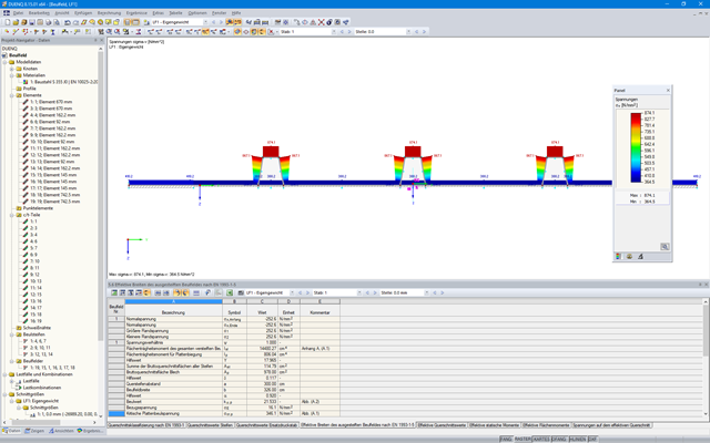
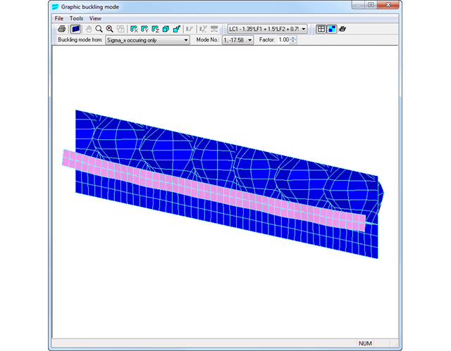
Design of a frame connection with taper and stiffened members. A stress analysis and a buckling stability analysis were carried out for the connection. To display the buckling results, the connection was converted into a separate model.
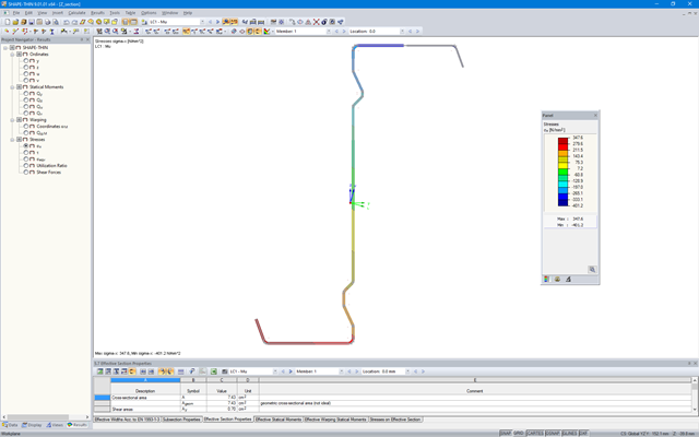
SHAPE‑THIN determines the effective cross-sections according to EN 1993‑1‑3 and EN 1993‑1‑5 for cold-formed sections. You can optionally check the geometric conditions for the applicability of the standard specified in EN 1993‑1‑3, Section 5.2.
The effects of local plate buckling are considered according to the method of reduced widths, and the possible buckling of stiffeners (instability) is considered for stiffened sections according to EN 1993‑1‑3, Section 5.5.
As an option, you can perform an iterative calculation to optimize the effective cross-section.
You can display the effective cross-sections graphically.
Read more about designing cold-formed sections with SHAPE-THIN and RF-/STEEL Cold-Formed Sections in the technical article "Design of Thin-Walled, Cold-Formed C-Section According to EN 1993‑1‑3".
Design of Thin-Walled, Cold-Formed C-Section According to EN 1993-1-3 More about RF-/STEEL Cold-Formed Sections_(2).png?mw=640&hash=0414bfe44045fc798e3774a0173332ca37424418)
General
- Beam to Column joint category: connection possible as joint of the beam to the column flange as well as joint of the column to the girder flange
- Beam to Beam joint category: design of beam joints as both moment-resisting end plate connections and rigid splice connections possible
- Automatic export of model and load data possible from RFEM or RSTAB
- Bolt sizes from M12 to M36 with strength grades 4.6, 4.8, 5.6, 5.8, 6.8, 8.8, and 10.9 as long as the strength grades are available in the selected National Annex
- Almost any bolt spacing and edge distances (a check of the allowable distances is performed)
- Beam strengthening with tapers or stiffeners on the top and bottom surfaces
- End plate connection with and without overlap
- Connection with pure bending stress, pure normal force load (tension joint), or combination of normal force and bending possible
- Calculation of connection stiffnesses and check if a hinged, semi-rigid, or rigid connection exists
End plate connection in a beam-column setup
- Joint beams or columns can be stiffened with tapers on one side or with stiffeners to one or both sides
- Wide range of possible stiffeners of the connection (for example, complete or incomplete web stiffeners)
- Up to ten horizontal and four vertical bolts possible
- Connected object possible as constant or tapered I-section
- Designs:
- Ultimate limit state of the connected beam (such as shear or tension resistance of the web plate)
- Ultimate limit state of the end plate at the beam (for example, T-stub under tensile stress)
- Ultimate limit state of the welds at the end plate
- Ultimate limit state of the column in the area of the connection (for example, column flange under bending – T-stub)
- All designs are performed according to EN 1993-1-8 and EN 1993-1-1
Moment-resisting end plate joint
- Two or four vertical and up to 10 horizontal bolt rows
- Joint beams can be stiffened with tapers on one side or with stiffeners to one or both sides
- Connected objects are possible as constant or tapered I-sections
- Designs:
- Ultimate limit state of the connected beams (such as shear or tension resistance of the web plates)
- Ultimate limit state of the end plates at the beam (for example, T-stub under tensile stress)
- Ultimate limit state of the welds at the end plates
- Ultimate limit state of the bolts in the end plate (combination of tension and shear)
Rigid splice plate connection
- For the flange plate connection, up to ten bolt rows one behind the other possible
- For the web plate connection, up to ten bolt rows possible each in vertical and horizontal directions
- Material of the cleat can be different from the one of the beams
- Designs:
- Ultimate limit state of the joint beams (for example, net cross-section in the tension area)
- Ultimate limit state of the cleat plates (for example, net cross-section under tensile stress)
- Ultimate limit state of the single bolts and the bolt groups (for example, shear resistance design of the single bolt)
In SHAPE-THIN 8, the effective cross-section of stiffened buckling panels can be calculated according to EN 1993-1-5, Cl. 4.5.
The critical buckling stress is calculated according to EN 1993-1-5, Annex A.1 for buckling panels with at least 3 longitudinal stiffeners, or according to EN 1993-1-5, Annex A.2 for buckling panels with one or two stiffeners in the compression zone. The design for torsional buckling safety is also performed.

- Modeling of the cross-section via elements, sections, arcs, and point elements
- Expansible library of material properties, yield strengths, and limit stresses
- Section properties of open, closed, or non-connected cross-sections
- Ideal section properties of cross-sections consisting of different materials
- Determination of weld stresses in fillet welds
- Stress analysis including design of primary and secondary torsion
- Check of c/t-ratios
- Effective cross-sections according to
- EN 1993-1-5 (including stiffened buckling panels according to Section 4.5)
-
 EN 1993-1-3
 -
EN 1999-1-1
-
 to DIN 18800-2
- Classification according to
-
EN 1993-1-1
-
EN 1999-1-1
-
- Interface with MS Excel to import and export tables
- Printout report

SHAPE-THIN calculates all relevant cross‑section properties, including plastic limit internal forces. Overlapping areas are set close to reality. If cross-sections consist of different materials, SHAPE‑THIN determines the effective cross‑section properties with respect to the reference material.
In addition to the elastic stress analysis, you can perform the plastic design including interaction of internal forces for any cross‑section shape. The plastic interaction design is carried out according to the Simplex Method. You can select the yield hypothesis according to Tresca or von Mises.
SHAPE-THIN performs a cross-section classification according to EN 1993-1-1 and EN 1999-1-1. For steel cross-sections of cross-section class 4, the program determines effective widths for unstiffened or stiffened buckling panels according to EN 1993-1-1 and EN 1993-1-5. For aluminum cross-sections of cross-section class 4, the program calculates effective thicknesses according to EN 1999-1-1.
Optionally, SHAPE‑THIN checks the limit c/t-values in compliance with the design methods el‑el, el‑pl, or pl‑pl according to DIN 18800. The c/t-zones of elements connected in the same direction are recognized automatically.
The results are displayed with references to EN 1993-1-5 or DIN 18800. In addition, RF-/PLATE-BUCKLING shows calculation results separately for the action of only one edge load as well as for the simultaneous effect of all edge loads.
In the case of several load cases, the governing load case is displayed separately. Thus, time-consuming comparison of calculation data is not necessary.
Window 2.5 lists the critical buckling load factors of all load cases and the respective buckling modes.
You can visualize the buckling modes and loads of the buckling panel in the graphic window. This facilitates a quick overview of the buckling modes and loads. Using the animation option, you can clearly represent the buckling behavior of stiffened plates.
Finally, it is possible to export all tables to MS Excel or in a CSV file.